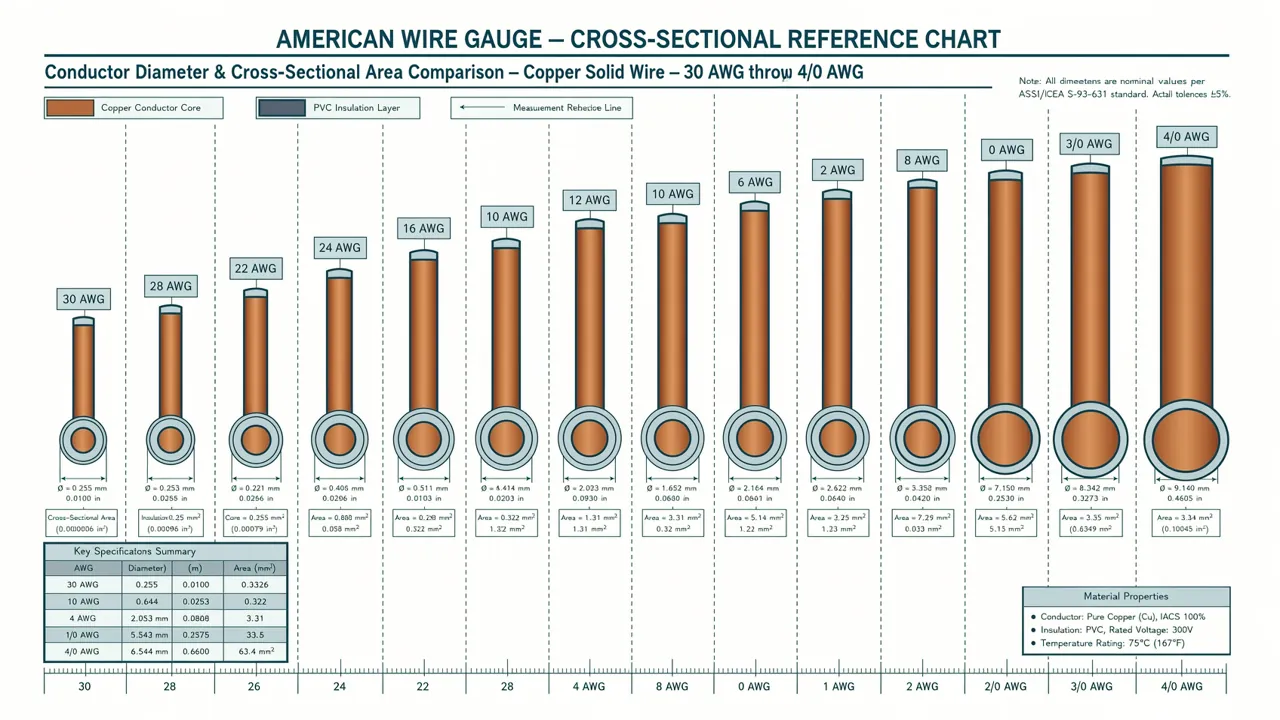
AWG 線規とは?
AWG(American Wire Gauge、米国線規)は導線の直径を表すための標準化された体系で、Brown & Sharpe 線規とも呼ばれます。1857 年にアメリカで導入され、現在でも北米の電子・電気業界における標準的な線径単位として使われています。
基本ルール:数字が大きいほど線は細い
AWG で最も混乱しやすいのがこの点です:
| ルール | 説明 |
|---|---|
| AWG 数字が大きい → 導線は細い | 24AWG は 18AWG よりずっと細い |
| AWG 数字が小さい → 導線は太い | 4/0(0000)が最も太い一般的な規格 |
| AWG が 3 減る → 断面積が 2 倍 | 12AWG の断面積 ≒ 9AWG の半分 |
| AWG が 10 減る → 断面積は約 10 倍 | 20AWG の断面積 ≒ 10AWG の 10 分の 1 |
なぜこうなっているの? AWG の数字は製造工程中に線材が引き抜きされるダイス(型)の穴番号に由来しています。番号が大きいほど穴が小さく、通る線も細くなるというわけです。
AWG vs メトリック(mm²)
中国では公制断面積(mm²)で線径を表すのが一般的ですが、アメリカやカナダなどでは AWG が広く使われています。以下のクイック換算リファレンスを参考にしてください:
| AWG | 断面積 (mm²) | 中国国標近似値 |
|---|---|---|
| 4/0 (0000) | 107.2 | 95–120 |
| 2/0 (00) | 67.4 | 70 |
| 1/0 (0) | 53.5 | 50 |
| 1 | 42.4 | 35–50 |
| 2 | 33.6 | 35 |
| 4 | 21.2 | 25 |
| 6 | 13.3 | 16 |
| 8 | 8.37 | 10 |
| 10 | 5.26 | 6 |
| 12 | 3.31 | 4 |
| 14 | 2.08 | 2.5 |
| 16 | 1.31 | 1.5 |
| 18 | 0.823 | 1 |
| 20 | 0.518 | 0.5–0.75 |
| 22 | 0.326 | 0.3 |
| 24 | 0.205 | 0.2–0.25 |
| 26 | 0.129 | 0.12 |
| 28 | 0.081 | 0.08 |
| 30 | 0.051 | 0.05 |
AWG 完全対照表(直径・断面積・抵抗・電流)
以下は AWG 4/0 から 30 までの完全な技術パラメータ表で、直径、断面積、銅線抵抗、および推奨電流容量が含まれています。
電流データ出典: NEC(米国国家電気規格)Table 310.16 銅導体 60°C/75°C 絶縁等級、および電子工学の実務経験値。
| AWG | 直径 (mm) | 直径 (inch) | 断面積 (mm²) | 銅抵抗 (Ω/km) | 定格電流 60°C (A) | 定格電流 75°C (A) |
|---|---|---|---|---|---|---|
| 4/0 (0000) | 11.684 | 0.460 | 107.2 | 0.1608 | 195 | 230 |
| 3/0 (000) | 10.404 | 0.410 | 85.0 | 0.2028 | 165 | 200 |
| 2/0 (00) | 9.266 | 0.365 | 67.4 | 0.2557 | 145 | 175 |
| 1/0 (0) | 8.251 | 0.325 | 53.5 | 0.3224 | 125 | 150 |
| 1 | 7.348 | 0.289 | 42.4 | 0.4066 | 110 | 130 |
| 2 | 6.544 | 0.258 | 33.6 | 0.5127 | 95 | 115 |
| 3 | 5.827 | 0.229 | 26.7 | 0.6465 | 85 | 100 |
| 4 | 5.189 | 0.204 | 21.2 | 0.8152 | 70 | 85 |
| 5 | 4.621 | 0.182 | 16.8 | 1.028 | — | — |
| 6 | 4.115 | 0.162 | 13.3 | 1.296 | 55 | 65 |
| 7 | 3.665 | 0.144 | 10.5 | 1.634 | — | — |
| 8 | 3.264 | 0.128 | 8.37 | 2.061 | 40 | 50 |
| 9 | 2.906 | 0.114 | 6.63 | 2.599 | — | — |
| 10 | 2.588 | 0.102 | 5.26 | 3.277 | 30 | 35 |
| 11 | 2.305 | 0.091 | 4.17 | 4.132 | — | — |
| 12 | 2.053 | 0.081 | 3.31 | 5.211 | 20 | 25 |
| 13 | 1.828 | 0.072 | 2.62 | 6.571 | — | — |
| 14 | 1.628 | 0.064 | 2.08 | 8.286 | 15 | 20 |
| 15 | 1.450 | 0.057 | 1.65 | 10.45 | — | — |
| 16 | 1.291 | 0.051 | 1.31 | 13.17 | 10 | — |
| 17 | 1.150 | 0.045 | 1.04 | 16.61 | — | — |
| 18 | 1.024 | 0.040 | 0.823 | 20.95 | 7 | — |
| 19 | 0.912 | 0.036 | 0.653 | 26.42 | — | — |
| 20 | 0.812 | 0.032 | 0.518 | 33.31 | 5 | — |
| 21 | 0.723 | 0.028 | 0.410 | 42.00 | — | — |
| 22 | 0.644 | 0.025 | 0.326 | 52.96 | 3 | — |
| 23 | 0.573 | 0.023 | 0.258 | 66.79 | — | — |
| 24 | 0.511 | 0.020 | 0.205 | 84.22 | 2.1 | — |
| 25 | 0.455 | 0.018 | 0.162 | 106.2 | — | — |
| 26 | 0.405 | 0.016 | 0.129 | 133.9 | 1.3 | — |
| 27 | 0.361 | 0.014 | 0.102 | 168.8 | — | — |
| 28 | 0.321 | 0.013 | 0.081 | 212.9 | 0.83 | — |
| 29 | 0.286 | 0.011 | 0.064 | 268.5 | — | — |
| 30 | 0.255 | 0.010 | 0.051 | 338.6 | 0.52 | — |
注意: "—" のついた AWG 規格は NEC 標準表に建築配線用の明確な定格電流値がありません。これらの中間規格は主に電子信号伝送に使用されます。
電流容量の詳しい解説
電流容量(Ampacity)とは?
電流容量とは、導線が許容温度上昇を超えない範囲で継続的に安全に流せる最大電流のことです。以下の要因に依存します:
- 導線断面積 — 断面積が大きいほど抵抗が小さく、より大きな電流を流せる
- 導体素材 — 銅 > アルミ(銅の導電率はアルミの約 1.6 倍)
- 絶縁材料の耐熱等級 — 一般的なものは 60°C、75°C、90°C
- 敷設環境 — 空中自由敷設 vs 配管敷設 vs 地中埋設
- 並列導線数 — 複数本の導線を並べて敷設する場合は定格を下げる必要がある
銅線 vs アルミ線 電流容量比較
| AWG | 銅線 75°C (A) | アルミ線 75°C (A) | 銅/アルミ比 |
|---|---|---|---|
| 14 | 20 | —* | — |
| 12 | 25 | 20 | 1.25 |
| 10 | 35 | 30 | 1.17 |
| 8 | 50 | 40 | 1.25 |
| 6 | 65 | 50 | 1.30 |
| 4 | 85 | 65 | 1.31 |
| 2 | 115 | 90 | 1.28 |
| 1/0 | 150 | 120 | 1.25 |
| 4/0 | 230 | 180 | 1.28 |
* NEC は建築配線における 14/10 AWG アルミ線の使用を認めていません(最小 12 AWG)。
経験則: アルミ線で銅線と同じ電流量を達成するには、2 つ上の AWG 規格が必要です。たとえば 12AWG 銅線 ≒ 10AWG アルミ線です。
環境温度による補正
上記の電流値は環境温度 30°C を基準としています。温度が更高い場合は補正係数を掛けます:
| 環境温度 | 補正係数 |
|---|---|
| 30°C | 1.00 |
| 35°C | 0.91 |
| 40°C | 0.82 |
| 45°C | 0.71 |
| 50°C | 0.58 |
| 55°C | 0.41 |
Arduino / 組み込みプロジェクトにおける AWG 選定
Arduino、ESP32、Raspberry Pi などの組み込みプロジェクトでは、建築配線のような太い線を使うことはまずありません。以下は一般的なシーンのおすすめ線径です:
ブレッドボードジャンパー線(DuPont 線)
| 用途 | 推奨 AWG | 最大電流 | 備考 |
|---|---|---|---|
| 信号線(GPIO、I2C、SPI) | 22–28AWG | 0.5–3A | DuPont 線は通常 22–24AWG |
| LED 電源供給 | 22–24AWG | 20–100mA | 単一 LED は数十 mA で十分 |
| モーター電源供給(小型) | 20–22AWG | 1–5A | TT モーター、サーボなど |
| ステッピングモーター | 20–22AWG | 1–2A/相 | 28BYJ-41、NEMA 17 など |
Arduino プロジェクト 常用線径クイックリファレンス
センサー電源供給(3.3V/5V, <100mA)  →  24–28AWG
サーボ制御線(SG90, ~150mA)         →  22–24AWG
DC モーター(1A 程度)               →  20–22AWG
LED テープ(5V, 1m あたり ~600mA)   →  18–20AWG
3D プリンターホットエンド電源(~5A)  →  16–18AWG
リチウム電池電源線(1S–4S, 10A+)   →  14–16AWG
ESP32 低消費電力プロジェクトでの線径考量
ESP32 のディープスリープなどの低消費電力プロジェクトでは、電流は 10μA レベルまで低下することがあり、この場合線径は電流容量よりも機械的強度が主な考慮事項になります。ただし注意点があります:
- RTC GPIO ウェイクアップピン:24–28AWG で十分
- センサー電源線:センサーの待機電流が 1mA を超える場合は 22AWG 以上を推奨
- ソーラー充電線:ソーラーパネルの出力は 1–2A に達することがあるため、18–20AWG を推奨
クイック換算式
AWG に対応する直径や断面積を自分で計算したい場合:
直径の計算式
直径 (inch) = 0.005 × 92^((36 - AWG) / 39)
直径 (mm)   = 直径 (inch) × 25.4
断面積の計算式
断面積 (mm²) = (π/4) × 直径² (mm)
Python 換算ツール
import math

def awg_to_diameter(awg):
    """AWG → 直径 (mm)"""
    diameter_inch = 0.005 * (92 ** ((36 - awg) / 39))
    return diameter_inch * 25.4

def awg_to_area(awg):
    """AWG → 断面積 (mm²)"""
    d = awg_to_diameter(awg)
    return math.pi / 4 * d ** 2

def awg_to_resistance(awg, length_m=1):
    """AWG + 長さ → 銅線抵抗 (Ω)"""
    area = awg_to_area(awg)
    # 銅の抵抗率: 1.68e-8 Ω·m = 0.0175 Ω·mm²/m
    return 0.0175 * length_m / area

# 使用例
for awg in [10, 12, 14, 16, 18, 20, 22, 24]:
    d = awg_to_diameter(awg)
    a = awg_to_area(awg)
    r = awg_to_resistance(awg, 1)
    print(f"{awg:2d}AWG: {d:.3f}mm, {a:.3f}mm², {r:.3f}Ω/m")
出力:
10AWG: 2.588mm, 5.261mm², 0.003Ω/m
12AWG: 2.053mm, 3.309mm², 0.005Ω/m
14AWG: 1.628mm, 2.081mm², 0.008Ω/m
16AWG: 1.291mm, 1.309mm², 0.013Ω/m
18AWG: 1.024mm, 0.823mm², 0.021Ω/m
20AWG: 0.812mm, 0.518mm², 0.034Ω/m
22AWG: 0.644mm, 0.326mm², 0.054Ω/m
24AWG: 0.511mm, 0.205mm², 0.085Ω/m
実践ケース:Arduino モータードライブプロジェクト
Arduino で NEMA 17 ステッピングモーターを駆動するとします。1 相あたりの電流は 1.5A、配線長は 30cm です。
# 電圧降下を計算
current = 1.5  # A
length = 0.3   # m(片道、実際は複線往復)
awg = 22       # 手持ちの線

r = awg_to_resistance(awg, length * 2)  # 複線往復
voltage_drop = current * r
power_loss = current ** 2 * r

print(f"22AWG, 30cm 複線往復:")
print(f"  抵抗: {r*1000:.1f}mΩ")
print(f"  電圧降下: {voltage_drop*1000:.1f}mV")
print(f"  電力損失: {power_loss*1000:.1f}mW")
出力:
22AWG, 30cm 複線往復:
  抵抗: 32.4mΩ
  電圧降下: 48.6mV
  電力損失: 72.9mW
結論: 22AWG で完全に問題なし。電圧降下はたったの 48.6mV(12V 電源に対して 0.5% 未満)、発熱もごくわずかです。
もし配線長が 2 メートルに伸びたらどうでしょうか?
length = 2.0  # m
r = awg_to_resistance(awg, length * 2)
voltage_drop = current * r
power_loss = current ** 2 * r

print(f"22AWG, 2m 複線往復:")
print(f"  抵抗: {r*1000:.1f}mΩ")
print(f"  電圧降下: {voltage_drop*1000:.1f}mV")

# より太い線に変更
awg = 18  # 18AWG にアップグレード
r = awg_to_resistance(awg, length * 2)
voltage_drop = current * r
print(f"18AWG, 2m 複線往復:")
print(f"  電圧降下: {voltage_drop*1000:.1f}mV")
出力:
22AWG, 2m 複線往復:
  抵抗: 215.8mΩ
  電圧降下: 323.8mV
18AWG, 2m 複線往復:
  電圧降下: 128.0mV
アドバイス: 配線長が 1 メートルを超える場合は、22AWG から 18AWG 以上にアップグレードして電圧降下を小さくするのがおすすめです。
AWG に関するよくある誤解
❌ 誤解 1:AWG 数字が大きいほど線が太い
真逆です。AWG の数字は引き抜きダイスの穴番号に由来しており、数字が大きいほど穴が小さく、線材も細くなります。覚えておくべきは:4/0 が最も太く、30 が最も細いということ。
❌ 誤解 2:断線さえしなければいい
導線の発熱は絶縁層の溶融だけでなく、火災の原因にもなります。継続的な負荷に対しては NEC 標準の 80% デレーティング(定格下げ) で使用すべきです。たとえば 14AWG の定格は 15A なので、長期負荷は 12A を超えないようにします。
❌ 誤解 3:アルミ線が安いからそのまま置き換えればいい
アルミ線は確かに安いですが、同じ電流量を達成するには銅線より2 つ上の AWG 規格が必要であり、さらにアルミのクリープ特性により接続部の緩みが生じやすいため、専用の酸化防止ペーストと圧着端子が必要です。
❌ 誤解 4:よりより線の方が単線より電流容量が大きい
同じ AWG 規格であれば、より線(stranded)と単線(solid)の断面積は同じで、電流容量もほぼ同じです。より線の利点は柔軟性にあり、電流能力にあるのではありません。
まとめ
| シーン | 推奨 AWG |
|---|---|
| Arduino/ESP32 ブレッドボードジャンパー線 | 22–24AWG |
| センサー信号線 | 24–28AWG |
| LED テープ電源供給 | 18–20AWG |
| 小型 DC モーター | 20–22AWG |
| 3D プリンターホットエンド | 16–18AWG |
| 家庭用 15A 回路 | 14AWG |
| 家庭用 20A 回路 | 12AWG |
| 家庭用 30A 給湯器 | 10AWG |
| 引込メイン線 | 4/0–2/0AWG |
Arduino プロトタイピングからスマートホーム配線まで、線径の正しい選択は安全と性能を保証する第一歩です。この記事をご自分の組み込みプロジェクトや電気工学設計のAWG 線規クイックリファレンスとしてお役立てください。